Product
Contact us

Sales manager:Tom Zhan
Tel:+0086 13632658537
Skype: zxp94520181
Whatsapp :+86 13632658537
Wechat: zxp94520181
Email:tom.zhan@primeda-telecom.com
www.primeda-telecom.com
HDMI to Fiber Extender
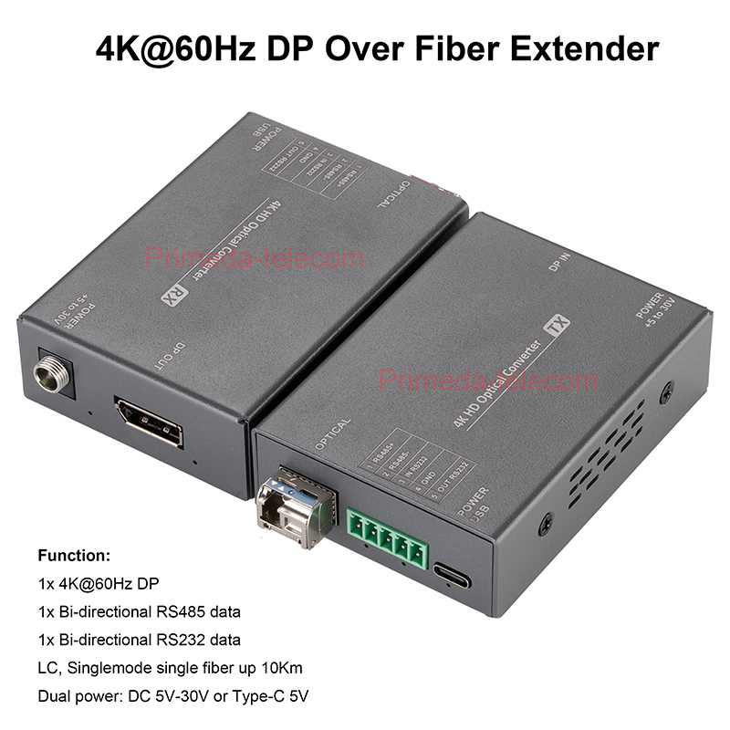

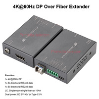

4K@60Hz Displayport DP Over Fiber Optic Extender with RS485 RS232 SFP LC Singlemode 10Km
PMD-4KDP-60Hz-2D-LC-10Km
The 4K DP over Fiber Converter can transmit 1 channel of 4K@60Hz DP and 1 bi-directional RS232 data and 1 bi-directional RS485 data through an optical fiber, realizing lossless transmission, no delay transmission distance up to 10Km.
Function:
1x 4K@60Hz DP
1x Bi-directional RS485 data
1x Bi-directional RS232 data
LC, Singlemode single fiber up 10Km
Dual power: DC 5V-30V or Type-C 5V
Feature:
The 4K DP over Fiber Converter can transmit 1 channel of 4K@60Hz DP and 1 bi-directional RS232 data and 1 bi-directional RS485 data through an optical fiber, realizing lossless transmission, no delay transmission distance up to 10Km.
Long Distance Transmission: Transmit DP signals up to 10 km over single-mode fiber or 300m over multi-mode fiber, perfect for large commercial and professional AV distribution setups. Each kit includes two 10G SFP+ (10 km) modules, allowing immediate deployment without additional purchases.
DP video complies with VESA DisplayPort 1.2 standard;
The device has a wide voltage power supply design of 5–30 V and provides two power supply modes: DC 5.5*2.1 and a USB Type-C interface. This makes it more flexible and convenient for use in various scenarios.
Support HDCP1.4/2.2/2.3 encryption to ensure content security; Support custom EDID, 3D and HDR display;
The video adopts EDID transparent transmission mode to ensure intelligent matching between the display device and the source device, avoiding display problems caused by incompatible parameters (such as resolution errors or image distortion), and improving compatibility and reliability;
Plug in SFP optical module design: supports hot swappable capability, compact design, strong flexibility, can replace multi-mode or farther distance modules according to actual needs, cost-effective and easy to maintain.
Rich status indicator lights: provide real-time feedback to help users quickly identify device status or potential issues.
Plug and play, no need for debugging;


Packing list
Attention
1.Lightning protection, static electricity, water proof,and grounding:
It is recommended that when install the device, consideration should be given to the impact of grounding by lightning, and take prevention measures. Strong static electricity will damage the optical device and data chip in the equipment. It is recommended that when plug/unplug the data port of the optical converter, please disconnect the power supply of the optical converter first.
2.Fiber and optical components:
Be careful when plugging the optical fiber as optical components of the optical converter is very fragile, and it should avoid causing damage to the optical components. It should be noted that the light source produced by the optical components of the optical converter will be harmful to eyes, so do not have direct eye contact with the optical components of optical converter. If you need to detect the optical power of the optical converter, please use the optical power meter.
3.Equipment and installation procedures:
(1)Optical fiber installation: please carefully insert the optical fiber into the optical fiber interface of the optical terminal after confirming that the optical fiber link meets the installation requirements.
(2)Equipment installation: The equipment can be distinguished between transmitter and receiver, and it is stated clearly on the label and printed on the chassis of the equipment.
(3)It is recommended to use a short fiber optic cable for the first time connecting test to ensure that all equipment functions are normal ,Then after that do long-distance transmission test
Power indicator is abnormal (POWER)
Answer: Check whether the power adapter meets the equipment requirements or the power adapter fails
Whether the socket is not tight or loose
Fiber indicator is abnormal (FIBER)
Answer: Check whether the optical fiber interface is loose and not plugged in
Check whether the optical fiber is too much attenuated
Video indicator is abnormal (VIDEO)
Answer: Check the signal source
Replace the video cable
Data indicator is abnormal (DATA)
Answer: Check the COM port, whether the baud rate is consistent
Check whether the serial port cable is connected backwards
1x 4K@60Hz DP
1x Bi-directional RS485 data
1x Bi-directional RS232 data
LC, Singlemode single fiber up 10Km
Dual power: DC 5V-30V or Type-C 5V
Attention:
Our company's DP optical transceiver (PMD-4KDP-60Hz-2D-LC-10Km) and HDMI optical transceiver (Search "PMD-4KHDMI-60Hz-RS232-LC-10Km" in our store) support interconnection (such as DP transmission, HDMI reception, or HDMI transmission, DP reception);
Feature:
The 4K DP over Fiber Converter can transmit 1 channel of 4K@60Hz DP and 1 bi-directional RS232 data and 1 bi-directional RS485 data through an optical fiber, realizing lossless transmission, no delay transmission distance up to 10Km.
Long Distance Transmission: Transmit DP signals up to 10 km over single-mode fiber or 300m over multi-mode fiber, perfect for large commercial and professional AV distribution setups. Each kit includes two 10G SFP+ (10 km) modules, allowing immediate deployment without additional purchases.
DP video complies with VESA DisplayPort 1.2 standard;
The device has a wide voltage power supply design of 5–30 V and provides two power supply modes: DC 5.5*2.1 and a USB Type-C interface. This makes it more flexible and convenient for use in various scenarios.
Support HDCP1.4/2.2/2.3 encryption to ensure content security; Support custom EDID, 3D and HDR display;
The video adopts EDID transparent transmission mode to ensure intelligent matching between the display device and the source device, avoiding display problems caused by incompatible parameters (such as resolution errors or image distortion), and improving compatibility and reliability;
Plug in SFP optical module design: supports hot swappable capability, compact design, strong flexibility, can replace multi-mode or farther distance modules according to actual needs, cost-effective and easy to maintain.
Rich status indicator lights: provide real-time feedback to help users quickly identify device status or potential issues.
Plug and play, no need for debugging;
Packing list
| Number | Name | Unit | Quantity |
| 1 | Transmitter | pcs | 1 |
| 2 | Receiver | pcs | 1 |
| 3 | Video SFP module | pair | 1 |
| 4 | 5P industrial terminal interface 3.81mm | pcs | 2 |
| 5 | 12V1A, DC5.5*2.1 power adapter | pcs | 2 |
| 6 | User’s manual | pcs | 1 |
| 7 | Warranty card/certificate | pcs | 1 |
Attention
1.Lightning protection, static electricity, water proof,and grounding:
It is recommended that when install the device, consideration should be given to the impact of grounding by lightning, and take prevention measures. Strong static electricity will damage the optical device and data chip in the equipment. It is recommended that when plug/unplug the data port of the optical converter, please disconnect the power supply of the optical converter first.
2.Fiber and optical components:
Be careful when plugging the optical fiber as optical components of the optical converter is very fragile, and it should avoid causing damage to the optical components. It should be noted that the light source produced by the optical components of the optical converter will be harmful to eyes, so do not have direct eye contact with the optical components of optical converter. If you need to detect the optical power of the optical converter, please use the optical power meter.
3.Equipment and installation procedures:
(1)Optical fiber installation: please carefully insert the optical fiber into the optical fiber interface of the optical terminal after confirming that the optical fiber link meets the installation requirements.
(2)Equipment installation: The equipment can be distinguished between transmitter and receiver, and it is stated clearly on the label and printed on the chassis of the equipment.
(3)It is recommended to use a short fiber optic cable for the first time connecting test to ensure that all equipment functions are normal ,Then after that do long-distance transmission test
Troubleshooting
Power indicator is abnormal (POWER)
Answer: Check whether the power adapter meets the equipment requirements or the power adapter fails
Whether the socket is not tight or loose
Fiber indicator is abnormal (FIBER)
Answer: Check whether the optical fiber interface is loose and not plugged in
Check whether the optical fiber is too much attenuated
Video indicator is abnormal (VIDEO)
Answer: Check the signal source
Replace the video cable
Data indicator is abnormal (DATA)
Answer: Check the COM port, whether the baud rate is consistent
Check whether the serial port cable is connected backwards
- Online Service
-
