Product
Contact us

Sales manager:Tom Zhan
Tel:+0086 13632658537
Skype: zxp94520181
Whatsapp :+86 13632658537
Wechat: zxp94520181
Email:tom.zhan@primeda-telecom.com
www.primeda-telecom.com
3G/HD SDI Converters
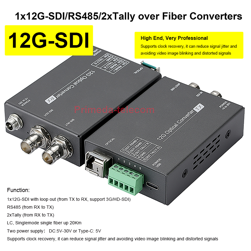


12G-SDI Video/RS485/2xTally over Fiber Optic Converters LC SFP up 10Km For UHDTV 4K 8K HDTV
PMD-12GSDI-D-2T-SFP
This sdi over fiber device to transmit 1-channel of forward directional 12G-SDI (from TX to RX) video signal, 1-channel reverse directional RS485 data (from RX to TXX) signal and 2-channel reverse directional tally function (one red light and one green light) with lossless, delay-free transmission of up to 20 km through a single optical fibre. The device has a wide voltage power supply design of 5–30 V and provides two power supply modes: DC 5.5*2.1 and a USB Type-C interface. This makes it more flexible and convenient for use in various scenarios.
High end & Super professional Portable 1x12G/3G-SDI Video /RS485/2xTally over Fiber Optic Converters, Highly recommended !
Most advantage: The device supports clock recovery, it can reduce signal jitter circuit, and process distorted signals, make a super stable signal transmission. it is much better than ordinary units in low costs in current marketing.
Product Introduction
This Portable 12G-SDI Video Multi-service Optical Fiber Transmission System was developed by our company and has independent intellectual property rights. It combines the advantages of similar products from both domestic and international markets with the actual demands of the market.
This sdi over fiber device to transmit 1-channel of forward directional 12G-SDI (from TX to RX) video signal, 1-channel reverse directional RS485 data (from RX to TXX) signal and 2-channel reverse directional tally function (one red light and one green light) with lossless, delay-free transmission of up to 20 km through a single optical fibre. The device has a wide voltage power supply design of 5–30 V and provides two power supply modes: DC 5.5*2.1 and a USB Type-C interface. This makes it more flexible and convenient for use in various scenarios.
The optical SFP module and core circuit are made of imported components and feature a multi-layer board design. The circuit is reliable and stable with strong anti-interference capabilities. The module is easy to install and debug, maintenance-free and designed to operate over a wide temperature range. As the transmission medium is optical fibre, it has excellent performance and is resistant to high temperatures and cold weather. It can effectively prevent strong electromagnetic radiation interference, lightning strikes, and power surges, greatly improving stability and reliability.
Product Features
1. Video compliance SMPTEST2082-1(12GUHD-SDI), ST2081-1(6GUHD-SDI), SMPTE424M, SMPTE292M,SMPTE259M,SMPTE297M,SMPTE305M, SMPTE310M standard.
2. The SFP module is suitable to pathological code video, support for irregular bit-rate signals and pathological video modes, ensuring video image transmission stable.
3. The device supports clock recovery, can reduce signal jitter circuit, and process distorted signals.
4. The input has cable equalization to compensate for cable transmission losses.
5. Data complies with EIA RS-485 standard and is transparently transmitted.
6. Support 2-channel Tally signal, one Tally is red light, another Tally is green light.
7. Wide voltage DC 5~30V design, and provides 2 interface power supply modes, DC and Type C.
8. Single-mode optical fiber transfer distance can far reach to 10km.


Transmitter (TX)-connection interface and Function

◐1 channel 12G-SDI video in,1 channel 12G-SDI video loop out.
◐12G-SDI pathological code video SFP module.
◐1-channel reverse RS485 data out.
◐2-cahnnel reverse TALLY function out.
◐DC 5.5*2.1/ DC 5~30V power in, the power interface supports a lock ring to prevent power cable falling off.
◑Support USB Type-C power 5V input.
| Number | Description | Function |
| 1 | OPTICAL | LC SFP module interface |
| 2 |
OUT RS485+ | RS485 + out |
| OUT RS485- | RS485 - out | |
| OUT TALLY R | TALLY Red light out | |
| GND | Ground wire | |
| OUT TALLY G | TALLY Green light out | |
| 3 | POWER USB | USB Type-C power in |
| 4 | SDI LOOP | SDI video loop out |
| 5 | SDI IN | SDI video in |
| 6 | POWER+5 to 30V | DC 5.5*2.1/ 5~30V power in |
Receiver (RX)- Connection interface and Function

◑2 channels same 12G-SDI video out.
◑12G-SDI pathological code video SFP module.
◑1-channel RS485 data in.
◑2-channel TALLY function in.
◑DC 5.5*2.1/ DC 5~30V power in, the power interface
supports a lock ring to prevent power cable falling off.
◑Support USB Type-C power 5V input.
| Number | Description | Function |
| 1 | OPTICAL | LC SFP module interface |
| 2 |
IN RS485+ | RS485 + in |
| IN RS485- | RS485 - in | |
| IN TALLY R | TALLY Red light in | |
| GND | Ground wire | |
| IN TALLY G | TALLY Green light in | |
| 3 | POWER USB | USB Type-C power in |
| 4 | SDI OUT | SDI video out |
| 5 | SDI OUT | SDI video out |
| 6 | POWER+5 to 30V | DC 5.5*2.1/ 5~30V power in |
Connecting Drawing Example

For reference only
It can be mounted into your camera with the hot shoe base


Product Data Sheet
| Functional Description: 12G-SDI video in with loop out +1-channel reverse RS485 data+ 2-channel reverse tally | |||||||||||||||
| Model: 1x12G-SDI/RS485/2xTally over Fiber Converters | |||||||||||||||
| Fiber parameter | |||||||||||||||
| Wavelength | 1270/1330nm | SFP module rate | 12Gbps | Fiber connector | LC | Distance | Single mode 10km | ||||||||
| Video parameter | |||||||||||||||
| Standard protocol | SMPTEST2082-1, ST2081-1, SMPTE424M, SMPTE292M, SMPTE259M, SMPTE297M, SMPTE305M, SMPTE310M | SMPTE rate | 270Mbit/s, 1.48Gbit/s, 2.97Gbit/s, 5.94Gbit/s, 11.88Gbit/s | ||||||||||||
| Support resolution | 4K60Hz backward compatibility | Pathological code | Support | Clock recovery | Support | Cable distance | <70M | ||||||||
| Data parameter | |||||||||||||||
| RS485 standard | EIA RS-485 | Transmission method | Reverse data transmission | Baud rate | 0~115200Kbps | Bit error rate | <10^-9 | ||||||||
| Pull-up resistor | 4.7 kΩ | Pull-down resistor | 4.7 kΩ | Termination resistor | 120 kΩ | ||||||||||
| Tally parameter | |||||||||||||||
| Level type | TTL(5V)/LVTTL(3.3V) | Input level range | 3.3V~12V | Output level range | 0V or 3.3V | Default state | No voltage out (0V) | ||||||||
| Power parameter | |||||||||||||||
| Power supply | DC 5.5*2.1/ USB Type-C | Input voltage | 5~30V power in | Overload protection | Yes | Power dissipation | <2W | ||||||||
| Shell parameter | |||||||||||||||
| The shell metal | Aluminium alloy | Product size | 87.3*61.9*24mm | Product net weight (unit: pair) | 0.35KG | Way to install | Desktop/ 1/4 hot shoe screw | ||||||||
| Packing parameter | |||||||||||||||
| Packing | Kraft paper | Packing size | 277 x 219 x 54 mm | Packing weight | 0.7KG | ||||||||||
| Other parameter | |||||||||||||||
| Operating temperature | -20°C ~+70°C | Storage temperature |
-40°C ~85°C | Relative humidity | From 5 to 95% (non-condensing) | Working life | >100000 hours | ||||||||
Packing list
| Number | Name | Unit | Quantity |
| 1 | Transmitter | pcs | 1 |
| 2 | Receiver | pcs | 1 |
| 3 | 12G pathological code video SFP module | pair | 1 |
| 4 | 5P industrial terminal interface 3.81mm | pcs | 2 |
| 5 | 12V1A, DC5.5*2.1 power adapter | pcs | 2 |
| 6 | User’s manual | pcs | 1 |
Attention
Lightning protection, static electricity and grounding:
It is recommended that when install the device, consideration should be given to the impact of grounding by lightning, and take prevention measures. Strong static electricity will damage the optical device and data chip in the equipment. It is recommended that when plug/unplug the data port of the optical converter, please disconnect the power supply of the optical converter first.
Fiber and optical components:
Be careful when plugging the optical fiber as optical components of the optical converter is very fragile, and it should avoid causing damage to the optical components. It should be noted that the light source produced by the optical components of the optical converter will be harmful to eyes, so do not have direct eye contact with the optical components of optical converter. If you need to detect the optical power of the optical converter, please use the optical power meter.
Equipment and installation procedures:
(1)Optical fiber installation: please carefully insert the optical fiber into the optical fiber interface of the optical terminal after confirming that the optical fiber link meets the installation requirements.
(2)Power amplifier audio signal cannot be directly given to the transmitter, which will lead to the burning machine.
(3)Equipment installation: The equipment can be distinguished between transmitter and receiver, and it is stated clearly on the label and printed on the chassis of the equipment.
- Online Service
-
